
") ĪudioSampleLR = AudioSampleLR = 0xAA55 Serial.println("erreur config horloge periph I2S. If (HAL_RCCEx_PeriphCLKConfig(&PeriphClkInitStruct) != HAL_OK) with HSI, leads to 48.08 KHz Word clock - adjust +/- 1 for fine tuning or use crystal (HSE) PeriphClkInitStruct.PeriphClockSelection = RCC_PERIPHCLK_I2S RCC_PeriphCLKInitTypeDef PeriphClkInitStruct If(SampleCounter FC = FS * 256 (or 12.288 MHz with FS = 48k) Void HAL_I2S_TxCpltCallback(I2S_HandleTypeDef *hi2s) Void HAL_I2S_TxHalfCpltCallback(I2S_HandleTypeDef *hi2s) HAL_NVIC_SetPriority(DMA1_Stream4_IRQn, 2, 0) SPI2 TX (used for I2S) is DMA Controller #1 (out of 2) stream 4 channel 0 AN4031 ST : table of DMA instance (controller #) vs channel vs peripheral

DMA1_Stream4_IRQn interrupt configuration GPIO_InitStruct.Alternate = GPIO_AF6_I2S2ext External SD (full duplex, incoming I2S) GPIO_InitStruct.Speed = GPIO_SPEED_FREQ_LOW GPIO_InitStruct.Alternate = GPIO_AF5_SPI2 GPIO_InitStruct.Pin = GPIO_PIN_12 | GPIO_PIN_13 | GPIO_PIN_15

This should work on a naked nucleo if a fellow member wants to test for us We don’t use the codec yet, we only instanciated the object but it can be avoided for testing. h file where you define what to compile with and what not
#Gpio led3 nucleo f401re mod
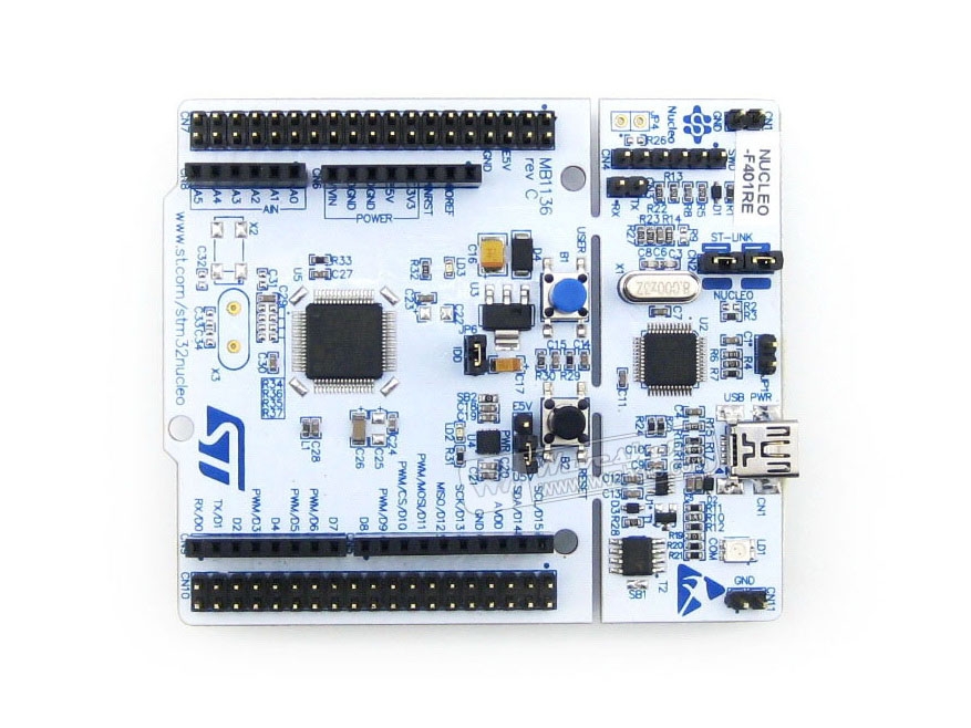
The only mod we made to the stock STM32 arduino toolchain is to enable the I2S (and the dma I think) in the core config. I’ve overriden the weak IRQ handles and the I2S callbacks, but so far, I don’t think I get in them. My guess is that the IRQ is triggered at the end of the dma transaction but goes to either a fault trap or in the never. When we launch the DMA for the first I2S transaction, the number of samples decided actually go out (master clock, word clock and samples are generated) then it freezes and the main loop isn’t responsive. The main loop mirrors the switch state to the onboard led to check it’s still running.
#Gpio led3 nucleo f401re code
The code is very basic so far but I don’t have a debugger to check what is happening. Happy to post our start code and try to get some help from this place where we’ve been reading quite a fair bit and learned a lot from (cheers). Now we’re adding the DMA and the board freezes. We’ve been following a proper learning curve about I/O’s configuration, clock settings etc and even got the I2S to work in polling mode and we could get the samples out, so SPI2 / I2S is properly configured We need to work with I2S and DMA to generate waveforms. We are using the STM32 duino to get trained on something that started as a “simple” project but we’re stumped. ‘Nucleo’ STM32F031K6 board with a button.As posted in the welcome thread, ARM noob here, our lab is migrating from 15 years of dev with microchip 8 and 16 bit MCU to ARM mcu. The green ‘LD3’ LED is attached to pin B3 on the board. The 100nF capacitor across the button should help reduce noise, one side of the button connects to ground through a jumper wire, and I put a 470Ω resistor between the other side of the button and pin B1. Strangely, the B1 pin is labeled ‘D6’ on the Nucleo boards I think that ST wanted to use the same footprint and labeling as the popular Arduino Nano. You can find the actual pin mappings in section 6.11 of this reference document, or they’re also printed on the informational card that comes with the board. The resistor and capacitor are both optional – they’re just a very simple form of debouncing. The STM32 chips have a lot of functionality which is not easy to represent in the standard C language. It has a number of hardware “Peripherals” to make it easier for you write programs which interact with the real world. They can do things like speak common communication protocols with other chips, run actions on timers, and send general-purpose signals to the pins connected to the chip. The way that we read and program these peripherals is to check and set certain values at specific memory addresses. For example, in this tutorial we will set a bit to 1 in an “Output Data Register” to pull a pin’s voltage high enough to turn on an LED, and reset the same bit to 0 to pull the pin to ground and turn the LED off.
#Gpio led3 nucleo f401re free
The companies which make these chips – ST Microelectronics in this case – usually also provide free header files which have definitions for which memory addresses go to which peripherals, and which bits do what.


 0 kommentar(er)
